

July 09, 2010
The Slimline hits Wall Street Journal
Big Happenings at EAC
It's been way too long since EAC Product Development has done some posting here. There are great things happening at EAC, specifically in the Design group.
1. We have a new addition to the team, Matthew Kunkel. He brings years of experience in design as well as systems engineering to our team.
2. EAC has hired a individual specific to growing the relationships needed to gain and win design projects. He is based out of the Milwaukee area and has been doing this type of relationship management for 15+ years. Scott Moeller is going to be a huge asset to the EAC team.
3. Next week July 12-17 is the yearly summer corporate training week. The whole company gets together to catch up and do some training/education on various topics. As a side benefit we get some great food (thanks to our resident chef Edie Siemens) and have some down time at the yearly picnic.
March 19, 2010

December 29, 2009
Staircase is a Wrap
A while back I had posted some pictures of an immaculate steel staircase being built. We were asked to create a 3D model along with the drawings and prints so that the welder could put this thing together properly. Here are a few images of the final piece.


December 14, 2009
SunArx’s Solar Trackers On Track Through Simulation and Analysis
Wanted to throw my guys a nice pat on the back. About a year ago we worked on a solar panel tracking system, not the electronics but the mechanism and strength of it. Its on the market now and our marketing department put together a nice article that got published in a couple different e-zines.
Take a look it's pretty interesting.

September 03, 2009
Staircase Development

The PDC team has started work on an architectural project, a first for us. An extravagant residential staircase is being developed from structural and plate steel.

The team is utilizing Pro/E to create the stairs so that the individual steel pieces can be documented and data may be provided to the manufacturer. The manufacturer will then use the data to cut the steel parts with his torch.
We are just getting started, more images to come!
August 05, 2009
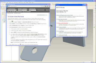
In Depth Help Files
PTC has a help topic collection that is far more in depth and broken down into modules. These documents explain everything from what each button does to the theory behind the Mechanica solver.
You can find the files here.
Create a Fillet Weld in Pro/E
Earlier this week a customer was having difficulty creating and showing a fillet weld in Pro/E WF 4. I put together a quick how to create a fillet weld and decided to post it here for the benefit of others. The steps are valid for previous versions of Pro/E WF but for WF 5 the Weld interface has been updated to utilize the dashboard like an extrusion or revolve feature so the steps are a little different for that.
Steps to Create a Fillet Weld
1. Select APPLICATIONS, WELDING from the Pro/E drop down menu.
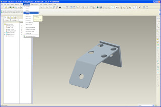
2. Select the WELD FEATURE from the tool bar or from the INSERT drop down menu.
a. Define the Weld parameters/type in the WELD DEFINITION dialogue box.

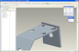
3. For a fillet weld select a set of surfaces that are in the same plane. This example shows only one surface being selected.
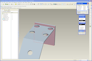
a. Select DONE REFS when you are done selecting the first set of surfaces.
4. For a fillet weld select a second set of surfaces that are in the same plane.
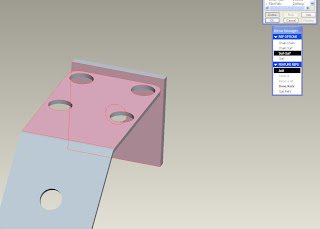
a. Select DONE REFS when you are done selecting the first set of surfaces.
5. Specify if you want the weld to be continuous, intermittent, the entire length, or set the ends.
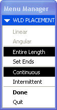
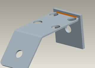
6. Specify the material side for the weld. The arrow points in the direction the weld will be added.
7. At this point specify any other options for the weld or hit the OK button to complete the weld.
8. For additional information about welds search the Pro/E help functionality or PTC's Knowledge Base.
1. Select APPLICATIONS, WELDING from the Pro/E drop down menu.

2. Select the WELD FEATURE from the tool bar or from the INSERT drop down menu.
a. Define the Weld parameters/type in the WELD DEFINITION dialogue box.

3. For a fillet weld select a set of surfaces that are in the same plane. This example shows only one surface being selected.

a. Select DONE REFS when you are done selecting the first set of surfaces.
4. For a fillet weld select a second set of surfaces that are in the same plane.

a. Select DONE REFS when you are done selecting the first set of surfaces.
5. Specify if you want the weld to be continuous, intermittent, the entire length, or set the ends.

6. Specify the material side for the weld. The arrow points in the direction the weld will be added.

7. At this point specify any other options for the weld or hit the OK button to complete the weld.

8. For additional information about welds search the Pro/E help functionality or PTC's Knowledge Base.

August 03, 2009
Free Lunch - Start Parts and Formats
So it was my turn to perform the Friday Free Lunch here at EAC. The topic was Start Parts and Formats. This is something not new to me at all. We in the PDC do this type of setup and configuration for many of our customers and in fact have a small defined consulting engagement set up already for this.
If you are interested in having EAC do this please contact us or your current Sales Representative.
If you would like to download the standard borders that were discussed, please click here.
There were some remaining questions from the webinar and I'll try to get them all answered here.

Q: Does the analysis feature in the footer cause the model to be marked as modified? This would be a disadvantage for using it in Windchill. For clarification, it would mark model as modified just by retrieving it into session?
A: If the analysis feature is modified (the model must have been modified) the model becomes modified and then the answer is yes. You could also investigate setting that feature as read-only, to stop this behavior. By default by retrieving a model in session it is not marked as modified.
Q: Are parameters case-sensitive? (thinking of attributes in Windchill)
A: I would say no they are not. Even if you type them in lowercase or a combination of upper and lower, once you save the newly added parameters, they become upper case. The attributes in Windchill are mapped to the parameters in the Pro/E Data.
Q: Is there a difference between renaming a datum plane in the model tree as opposed to renaming in properties?
A: No, there is no difference in renaming the model in the model tree versus using the feature property dialog box to rename the datum plane or any other feature.
Q: Is everything we learn today relative to Wildfire 3?
A: Yes, the items covered today are the same as in Wildfire 3.0.
Q: Can you use bitmaps for symbols?
A: No, but you can use other imported data such as AutoCAD files.
Q: I missed it, how do you start creating a start part?
A: I would recommend starting from the default parts provided by PTC. But if you want to create a new file simply create a new file, uncheck the "USE DEFAULT TEMPLATE", choose empty for your template and then begin inserting the coordinate system, datum planes, parameters, relations, layers and views.
Q: How do you save these files to reuse them?
A: Start parts and format files are saved just like any other file in Pro/Engineer. You can either place them in the default install location or in your config file located central location.
Q: How about the config.sup file? How do you create this file?
A: The config.sup file is simply a config.pro file that is renamed to the .sup extension. An option that is set in the config.pro file cannot override the config.sup file.
Q: If the parameters are locked how can they be unlocked? Pasword?
A: Locked parameters are typically created by a data management system or a relation. They cannot be unlocked unless you remove the relation that is driving/creating the parameter. Data Management parameters cannot be unlocked.
Q: What does the Designate Box do?
A: It really does two things, first it allows you to populate the parameter as you are creating the model. And second it allows you to tie it to attributes in Intralink or Windchill based PDM systems.

Q: Should parameters for drawing templates be put into the model or the drawing? Or does it even matter where they reside?
A: It really depends on how you want the data controlled. We prefer to have all the necessary parameters in the model as this is your source. If you want to have drawing parameters created they will only be able to be used on that particular drawing.
Q: For logos, can you import from an AutoCAD or Jpeg file?
A: You can import autoCAD data as sketch entities and use them. You can insert a BMP as an Object but not a JPEG. To do this go to INSERT>OBJECT.

Q: Where do you open this format from?
A: Tthe format file is opened from the default location
Q: We use mainly "STRING" when setting up parameters, is there some way to change the order of prompts? Can "STRING" be ahead of INTEGER and REAL NUMBER?
A: Sorry, no. There are sorted alphabetically.

Thanks to everyone for your attendance, hopefully the content shown was of use.
August 01, 2009
New Layout
Well it's time. I've searched over and over and can't find just the right layout to use or template to start with. So we will start with a simple white background and see where we go from here.
We (the PDC Team) hope to update this blog at least weekly. Hopefully it will contain useful information for you.
Check back often.
Subscribe to:
Comments (Atom)


